1.Focal Length of Optical Systems
Focal length is a very important indicator of optical system, for the concept of focal length, we more or less have an understanding, we review here.
The focal length of an optical system, defined as the distance from the optical center of the optical system to the focus of the beam when parallel light incident, is a measure of the concentration or divergence of light in an optical system. We use the following diagram to illustrate this concept.

In the above figure, the parallel beam incident from the left end, after passing through the optical system, converges to the image focus F’, the reverse extension line of the converging ray intersects with the corresponding extension line of the incident parallel ray at a point, and the surface that passes this point and is perpendicular to the optical axis is called the back principal plane, the back principal plane intersects with the optical axis at point P2, which is called the main point (or the optical center point), the distance between the main point and the image focus, it is what we usually call the focal length, the full name is the effective focal length of the image.
It can also be seen from the figure that the distance from the last surface of the optical system to the focal point F’ of the image is called the back focal length (BFL). Correspondingly, if the parallel beam is incident from the right side, there are also concepts of effective focal length and front focal length (FFL).
2. Focal Length Testing Methods
In practice, there are many methods that can be used to test the focal length of optical systems. Based on different principles, the focal length testing methods can be divided into three categories. The first category is based on the position of the image plane, the second category uses the relationship between magnification and focal length to obtain the focal length value, and the third category uses the wavefront curvature of the converging light beam to obtain the focal length value.
In this section, we will introduce the commonly used methods for testing the focal length of optical systems::
2.1 Collimator Method
The principle of using a collimator to test the focal length of an optical system is as shown in the diagram below:
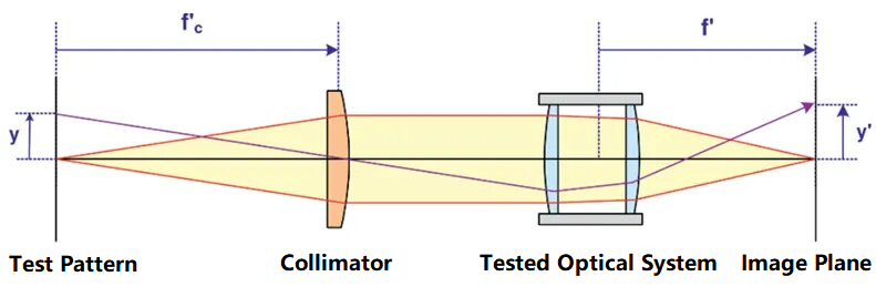
In the figure, the test pattern is placed at the focus of the collimator. The height y of the test pattern and the focal length fc’ of the collimator are known. After the parallel beam emitted by the collimator is converged by the tested optical system and imaged on the image plane, the focal length of the optical system can be calculated based on the height y’ of the test pattern on the image plane. The focal length of tested optical system can uses the following formula:

2.2 Gaussian Method
The schematic figure of Gaussian method for testing the focal length of an optical system is shown as below:
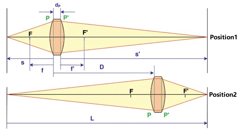
In the figure, the front and back principal planes of the optical system under test are represented as P and P’ respectively, and the distance between the two principal planes is dP. In this method, the value of dP is considered to be known, or its value is small and can be ignored. An object and a receiving screen are placed at the left and right ends, and the distance between them is recorded as L, where L needs to be greater than 4 times the focal length of the system under test. The system under test can be placed in two positions, denoted as position 1 and position 2 respectively. The object on the left can be clearly imaged on the receiving screen. The distance between these two locations (denoted as D) can be measured. According to the conjugate relationship, we can get:
At these two positions, the object distances are recorded as s1 and s2 respectively, then s2 - s1 = D. Through formula derivation, we can get the focal length of the optical system as below:

2.3 Lensometer
The Lensometer is very suitable for testing long focal length optical systems. Its schematic figure is as follows:
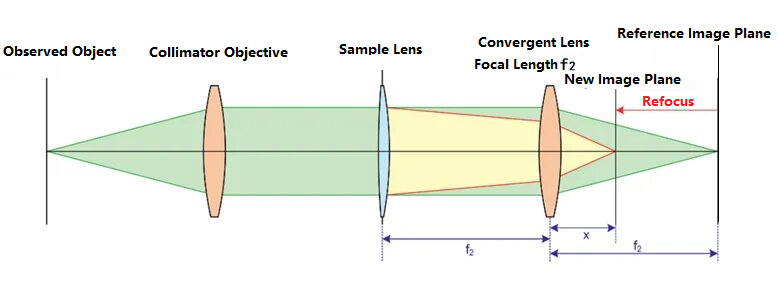
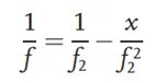
First, the lens under test is not placed in the optical path. The observed target on the left passes through the collimating lens and becomes parallel light. The parallel light is converged by a converging lens with a focal length of f2 and forms a clear image at the reference image plane. After the optical path is calibrated, the lens under test is placed in the optical path, and the distance between the lens under test and the converging lens is f2. As a result, due to the action of the lens under test, the light beam will be refocused, causing a shift in the position of the image plane, resulting in a clear image at the position of the new image plane in the diagram. The distance between the new image plane and the converging lens is denoted as x. Based on the object-image relationship, the focal length of the lens under test can be inferred as:
In practice, the lensometer has been widely used in the top focal measurement of spectacle lenses, and has the advantages of simple operation and reliable precision.
2.4 Abbe Refractometer
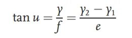
The Abbe refractometer is another method for testing the focal length of optical systems. Its schematic figure is as follows:
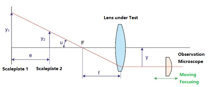
Place two rulers with different heights at the object surface side of the lens under test, namely scaleplate 1 and scaleplate 2. The corresponding scaleplates’ height are y1 and y2. The distance between the two scaleplates is e, and the angle between the ruler’s top line and the optical axis is u. The scaleplated is imaged by the tested lens with a focal length of f. A microscope is installed at the image surface end. By moving the position of the microscope, the top images of the two scaleplates are found. At this time, the distance between the microscope and the optical axis is denoted as y. According to the object-image relationship, we can get the focal length as:
2.5 Moire Deflectometry Method
The Moiré deflectometry method will use two sets of Ronchi rulings in parallel light beams. Ronchi ruling is a grid-like pattern of metal chromium film deposited on a glass substrate, commonly used for testing the performance of optical systems. The method utilizes the change in Moiré fringes formed by the two gratings to test the focal length of the optical system. The schematic diagram of the principle is as follows:
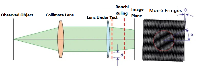
In the figure above, the observed object, after passing through the collimator, becomes a parallel beam. In the optical path, without adding the tested lens first, the parallel beam passes through two gratings with a displacement angle of θ and a grating spacing of d, forming a set of Moiré fringes on the image plane. Then, the tested lens is placed in the optical path. The original collimated light, after refraction by the lens, will produce a certain focal length. The curvature radius of the light beam can be obtained from the following formula:
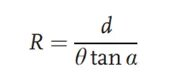
Usually the lens under test is placed very close to the first grating, so the R value in the above formula corresponds to the focal length of the lens. The advantage of this method is that it can test the focal length of positive and negative focal length systems.
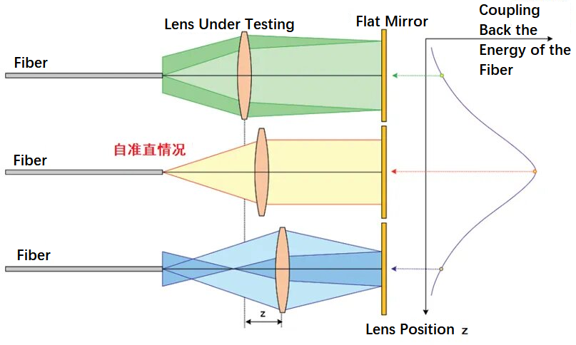
2.6 Optical Fiber Autocollimation Method
The principle of using the optical fiber autocollimation method to test the focal length of the lens is shown in the figure below. It uses fiber optics to emit a divergent beam that passes through the lens being tested and then onto a plane mirror. The three optical paths in the figure represent the conditions of the optical fiber within the focus, within the focus, and outside the focus respectively. By moving the position of the lens under test back and forth, you can find the position of the fiber head at the focus. At this time, the beam is self-collimated, and after reflection by the plane mirror, most of the energy will return to the position of the fiber head. The method is simple in principle and easy to implement.
3.Conclusion
Focal length is an important parameter of an optical system. In this article, we detail the concept of optical system focal length and its testing methods. Combined with the schematic diagram, we explain the definition of focal length, including the concepts of image-side focal length, object-side focal length, and front-to-back focal length. In practice, there are many methods for testing the focal length of an optical system. This article introduces the testing principles of the collimator method, Gaussian method, focal length measurement method, Abbe focal length measurement method, Moiré deflection method, and optical fiber autocollimation method. I believe that by reading this article, you will have a better understanding of the focal length parameters in optical systems.
Post time: Aug-09-2024


